NeoBracelet v3.0 by the Brain
This is a continuation of my original post which (back then) was just a proof of concept. Over the years I have improved the design and now I've come to a version that I use often and has proven to be very durable and reliable.
This project is worthwhile but is not at all easy. The circuit board construction is extremely difficult to achieve without error and still maintain a compact design. A small mistake can ruin most or all of your work.
Side Note:
This invention has been banned from Disneyland so I do not recommend bringing this along if you go. The extremely fat and rude security staff took me aside and told me these items were not allowed in because of the exposed wires that could be confused with a bomb or other nefarious devices. He even tried to tell me that my LED mickey ears were an infringement on Disney's brand despite the several hundred of custom mickey ears already in the park that were acquired on Etsy.
List of materials:
This tutorial requires knowledge of arduino microcontrollers. If you don't know how to upload code to arduino, you will need to locate a separate tutorial to get that setup. I am not covering that in this post.
Pro Trinkets will work but beware regular Trinkets and Gemma sized boards will not successfully run the code I provided. The board needs to have enough flash space to compile the code.
You can use smaller batteries but the energy capacity tradeoff IMO isn't worth it. Aside from that the smaller batteries are close to the same price and you will need more of them so overall the batteries I listed here are the best system so far.
Note the direction of the LED stips. There are arrows to show you which direction and thus which pixel is first in the sequence.
The code provided is at 25% brightness. Full brightness level is very bright and very often too bright in low light areas. use caution if you adjust the brightness level.
The bracelet will last quite a while if you don't wear it often. To test it, I wore the bracelet every day and it took ~3 months (90 days) before it started failing due to wear and tear. The most common point of failure is the part of the strip that bends in order to remove the bracelet by detaching it from the velcro. continuous bending of the strips will eventually cause them to break. the bracelet still works but the LEDs after that break point will not work.


This project is worthwhile but is not at all easy. The circuit board construction is extremely difficult to achieve without error and still maintain a compact design. A small mistake can ruin most or all of your work.
Obligatory Disclaimer:
While I shouldn't have to say this anyway....I am not responsible for
anything you do. I don't care if you burn your house down or worse.
This information is for educational purposes only and you are
responsible for your own actions.
Physical Warning:
This task does involve some soldering. If you have no desire to do
that, then you can find someone that knows how to solder or just go do a
different project. You can always locate your nearest Hackerspace and
there should be plenty of people there that can assist.
Copyright Warning:
This project is my intellectual property that I am giving to the open-source community for non-profit use only.Side Note:
This invention has been banned from Disneyland so I do not recommend bringing this along if you go. The extremely fat and rude security staff took me aside and told me these items were not allowed in because of the exposed wires that could be confused with a bomb or other nefarious devices. He even tried to tell me that my LED mickey ears were an infringement on Disney's brand despite the several hundred of custom mickey ears already in the park that were acquired on Etsy.
List of materials:
- One meter Adafruit Neopixels (144/meter) with black strips. Cheaper WS2812 strips are also available on amazon, but beware poor quality is easier to damage.
- One plain leather bracelet, black color is preferred.
- Alternative option: you can also purchase a chunk of medium strength leather and cut it to your needed length/width. Amazon has some decent choices, just make sure it's thick enough to be a decent bracelet. You can also buy a small sheet of leather at Michael's or other craft store. The leather must be strong enough to not bend much when holding it by one side parallel to the floor.
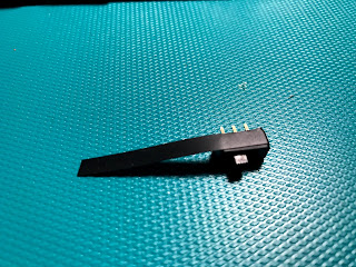
- One Adafruit Trinket Pro 3v or Arduino Pro Mini compatible. I do recommend the Trinket Pro as the quality is much higher and easier to use. But the Pro Trinket is larger than the board used in this demo. I used an arduino Pro Mini compatible because it was the correct fit. If you don't place the charger next to the arduino, then you have plenty of room for a Trinket Pro.
- Low voltage wire, threaded (NOT single core wire). Cat5 cable works great.
- 2-4 Li-Po batteries, 380-680mAh each
- LiPo battery charger
- Industrial strength velcro (black)
- Regular strength velcro (black)
- Soldering iron & solder
- One small on/off toggle switch
- Hot glue gun & hot glue
- Gorilla Glue, clear and normal (brown)
- Binder clips, small, medium, and large
- Heat shrink and heat gun
- Hair spray
- Electrical tape (black)
- Exacto knife
Notes
I do prefer Adafruit parts as they are made in the USA and way better quality. But in this guide I am using cheaper parts from China as I needed to save money in my prototyping. I built at least 4 of these before I arrived to a design that pleased and sparkled. Once you have the process down, invest in higher quality parts.This tutorial requires knowledge of arduino microcontrollers. If you don't know how to upload code to arduino, you will need to locate a separate tutorial to get that setup. I am not covering that in this post.
Pro Trinkets will work but beware regular Trinkets and Gemma sized boards will not successfully run the code I provided. The board needs to have enough flash space to compile the code.
You can use smaller batteries but the energy capacity tradeoff IMO isn't worth it. Aside from that the smaller batteries are close to the same price and you will need more of them so overall the batteries I listed here are the best system so far.
Note the direction of the LED stips. There are arrows to show you which direction and thus which pixel is first in the sequence.
The code provided is at 25% brightness. Full brightness level is very bright and very often too bright in low light areas. use caution if you adjust the brightness level.
The bracelet will last quite a while if you don't wear it often. To test it, I wore the bracelet every day and it took ~3 months (90 days) before it started failing due to wear and tear. The most common point of failure is the part of the strip that bends in order to remove the bracelet by detaching it from the velcro. continuous bending of the strips will eventually cause them to break. the bracelet still works but the LEDs after that break point will not work.
Assembly
First, cut off the ends of the wires of the Lipo batteries and splice them to some low voltage wire, basically extending the wires at least 12 inches.
If you bought some leather, cut it out a piece to fit the length of the batteries and leave room for the Arduino and breadboard at the end. See pictures in the steps ahead to get a better idea of how much space you need.


Spread out the batteries across the leather. Place one at the far left end, another 1cm to the right. Now leave a space of about 2 inches and place another, then 1cm and the last battery. The middle gap will be used later on. The last battery on the right should have a section of leather about 5 inches long. This is the circuit board area.
If you have only 2 batteries, just spread them apart evenly. I used four because it makes it easier to maintain a rounder shape when worn.
Position the batteries so the wires run along the top towards the center gap you made earlier. Once they are all in the correct positions, use some binder clips to hold them in place.
Splice all the wires together in the center gap and cut off the excess wire. Splice together all positive wires to become one single positive wire. Do the same for the negative wires. After that, splice together a new piece of wire to the center wires and run it along the bottom side of the bracelet towards the circuit board area.
Once all the wires are where they should be and everything looks rather clean, use the electrical tape to fasten the batteries to the leather which will also contain the wires. This is the better way as glue really doesn't work for this stage. The wire leading back to the circuit board area is you main power source. Make sure the wire reaches past the end of the leather so you know you have plenty of slack.


Cut the breadboard in 4 pieces and round off the edges. Place one piece at the blank end of the leather by the last battery. Cut the battery wire slack to an appropriate length to prepare it for soldering. Solder the positive wire to the first available row (in this picture, row 17). Solder the negative wire to the negative (blue) strip.

Now let's prepare the LEDs.
Cut your single LED strip of 144 LEDs into four pieces, 36 LEDs per piece. This is difficult as you have to leave room at the start of the strip for the soldering points. If the soldering points are not available after you cut the strip, that first LED cannot be used and you must cut it again. Use a pair of wire snippers to give it a clean cut right against the LED.

Now solder small wires onto each solder point. Be careful not to de-solder the nearby resistors or damage the LED. you will need a very thin solder tip.
One of the strips will have the original wires still attached. You don't want to use them as they are less flexible. Cut them off but leave the existing solder in place. Use that solder to attach your preferred smaller wires like the other strips.

Once the strip has its wires attached, you will want to glue the solder in place.
THIS IS CRITICAL. the bending of the bracelet will cause the soldered connections to loosen over time. You can use hot glue for a quick and solid reinforcement, but I recommend using the clear Gorilla glue as it's much stronger but still bends. However, Gorilla takes hours to dry.
NOTE: you can opt to glue them later, after they are soldered to the breadboard. if you make a mistake with the breadboard or cut the wires too short, it's possible to re-solder a new wire to the strip.
Be sure to test each strip before proceeding. Ensure all LED's light up and respond to data from your arduino.
After that, remove the sticker cover strip on the reverse side. Then take an exacto knife and carefully remove the sticky tape affixed to the reverse side. Once you have a clean back surface, you can proceed to the remaining strips and repeat.

Line up the LEDs in the same direction. Start with two and make sure the first LED is directly adjacent to the other strip's first LED. The strips usually have lines marked in the strip to help you line them up properly. When they are lined up, use some electrical tape to temporarily hold them in place as they are. Add the other strips and keep adding more tape. More is better.

You will end up with one large strip 4 LEDs wide.

Now flip it over and spread some clear Gorilla glue on the back side, a little will go a long way. Dont add too much to where it will leak into the front side. Place long pieces of electrical tape over the glue and allow it to dry.

Now attach the normal strength velcro to the other end of the LED strip. Measure the strip's width and cut multiple pieces of velcro to that length. As shown below, wrap the first piece around the edge of the LED strip. The velcro should cover the last row of LEDs and wrap around to the back side of the strip. Use clear gorilla glue to affix the velcro to the LED strip. Use a large binder clip to hold it down while it dries. Attach more pieces to the back of the LED strip adjacent to the first piece of velcro. Use gorilla glue again and let it dry.

Before you proceed, this is a good opportunity to coat the strips with some kind of waterproofing agent. A cheap option is hair spray, but you can find a glossy coat spray at Home Depot that does a great job and also makes the LEDs shine very well. hair spray tends to make them less shiny.
When the full set of strips is dried, you can now attach it to the breadboard. This can be difficult as you don't want the wires to have too much slack and they still need to be long enough to get to where you need them to be on the breadboard.
Solder the positive wires to the positive (red) strip, the negative wires to the negative (blue) strip, and the data wires can be evenly spread out to different rows on the breadboard (as shown below).

Now prepare the switch. Depending on the switch, you will need to "waterproof" it. by that I mean you need to ensure none of the glue can get inside. If it does it ruins the switch and could potentially ruin your entire project depending on how far along you are and how much glue was applied.
The image below shows some electrical tape wraped around. this didnt work as well for me. I ended up using hot glue and applying it very sparingly around the edges to plug up all the holes.

After that, cut off one of the three leads and solder a piece of wire to the two remaining leads. the wire should be about 6 inches long to allow for your preferred placement.
Solder one of the switch wires to the row that has the positive wire coming from the batteries. Leave the other wire alone for now. Add some hot glue to the soldered leads of the switch to give the solder some reinforcement.
Now solder wires to the battery charger. Then solder the other ends to the breadboard. The negative wire goes to the negative (blue) strip and the positive wire goes to the same row with the wire coming from the batteries. Ensure the charger's positive wire is not going straight to the positive (red) row of the breadboard.
In the picture below, the charger will be placed next to the Arduino at the end of the bracelet. This has caused problems for the charger as it is in a place where the charger will get bent from wearing the bracelet. So it is recommended you find room to place the charger somewhere else on the bracelet.

Do some tests here. The batteries should charge successfully. If the batteries have power, the switch should send power to the red row of the breadboard, so test that with an multimeter.
Now you can ready the arduino. Solder 6 inch pieces of wire into each of the following ports: 2,4,6,8, GND, VCC.

When that's done, solder the other wire attached to the switch into the RAW port on the arduino.
Now solder the remaining wires on the arduino into the breadboard.
Place the 2,4,6,8 wires into a row where you soldered in the data wires of each LED strip.
Solder the VCC wire into the positive (red) row of the breadboard.
Solder the GND wire into the negative (blue) row of the breadboard.

With everything attached, the arduino should now power on/off when the switch is toggled.
Now you can flash your arduino board with the bracelet code. The arduino I have listed does not have a usb port, so you will need to have an FTDI to usb cable or you can buy an arduino that is small enough and still has a USB port. Open the file below and upload the code to the arduino.
https://github.com/bramuno/neopixel/blob/master/NeoBracelet.cpp
If everything connected well, your LEDs should be lighting up when the switch is toggled on.

Now it's time to glue down the boards. ensure there is enough room for the breadboard and arduino/charger and note where you will be gluing them. For this part, I advise using the normal gorilla glue to glue the underside of the boards to the leather. The normal (brown) glue is very strong and does not bend. First glue the breadboard but use less than what you need because the glue WILL EXPAND as it dries. Give it time to dry and then come back and do the other two boards.
Likely the glue will expand and glue all the boards together. At this point it's ok to bend the leather to separate the arduino from the breadboard's adjacent glue.
Now find a place for the switch to go. Drop some brown gorilla glue there and place the switch in the glue. Use a medium or small binder clip to hold it in place while it dries. When dried, the switch should be set but not too well. Drop some more glue on the switch and let it dry.
Now cut a piece of industrial strength velcro (fuzzy side) to fit over the breadboard. it should start at the end of the first LED on the strips and proceed to far end of the breadboard. It can go longer and over the arduino, but that can add to other problems. Place some clear gorilla glue on the breadboard wires and areas where the velcro needs to grip. Attach the velcro and use large binder clips to hold in place. Allow time to dry.

CAUTION: Do not use both sides of the industrial strength velcro. It is too powerful and will rip apart your connections. Using both industrial and regular velcro in combination (in my opinion) works best by providing the strongest hold without damaging the bracelet.
When it's all dried, ensure the switch still moves freely and the arduino still powers on. If the switch doesn't move, it means glue made it inside and you have to somehow go back and fix it.
If the switch moves and powers on the bracelet and all the LEDs are working, then you are all done. Like I said there are many places to mess up so hopefully you made it through.


Comments
Post a Comment